


Key Takeaways
- Load cell calibration is a measurement activity that quantifies error; it does not "fix" the load cell. The most valuable data is the "as-found" reading, which shows how the cell has performed since its last service.
- Shunt calibration is widely misunderstood. It verifies the electrical signal path but applies no mechanical force, meaning it cannot detect mechanical issues like creep, bonding failure, or structural damage.
- A proper calibration involves a multi-point test with both ascending and descending loads to measure nonlinearity and hysteresis, which single-point checks completely miss.
- There is no universal calibration interval. The right interval is determined by analyzing drift history from past certificates, application risk, and environmental severity not by a fixed annual schedule.
- An ISO/IEC 17025 accredited calibration certificate is your proof of measurement integrity. It must include as-found/as-left data, the reference standard's traceability, and a statement of measurement uncertainty.
A quality manager receives a calibration certificate for a critical process load cell. The summary box says "PASS." They file the certificate, update the asset record, and move on. Months later, a product quality issue triggers an investigation, revealing that the measurements from that process have been systematically off. When they pull the certificate again, the answer is right there in the data table: the as-found readings showed the cell was already drifting at the upper end of its range. No one flagged it because no one read beyond the pass/fail summary.
This scenario is the most common way calibration programs fail. Organizations treat load cell calibration as a compliance checkbox rather than a diagnostic opportunity.
Let's be clear: calibration does not fix a load cell. It measures how that load cell is actually performing. Its value is in understanding what the data reveals about your measurement integrity. When a load cell drifts beyond tolerance between calibration cycles and the drift is only discovered at the next scheduled service, every measurement taken in that window becomes suspect. The cost of investigating or recalling affected product often dwarfs the cost of a properly structured calibration program from a provider like Cal-Cert that captures as-found data and tracks drift history.
This guide explains the load cell calibration process from a practitioner's perspective. We will cover:
- The multi-point process and what the data reveals.
- The critical difference between true force calibration and electrical simulation.
- The real causes of drift and how to set defensible calibration intervals.
- How to read the certificate that makes your measurement defensible in an audit.
What Load Cell Calibration Actually Determines
The first and most critical point to understand is that calibration is a measurement activity, not a correction activity. Calibrating a load cell only compares its output against a known, traceable reference standard and documents the deviation. It answers the question: "How accurate is this instrument right now?"
Calibration quantifies the relationship between applied force and load cell output; adjustment changes that relationship. Conflating the two in a quality system means you may be erasing as-found data before it is recorded, which destroys your ability to evaluate drift or detect developing mechanical problems.
Consider a technician calibrating a 50 kN compression load cell. The calibration result is the set of deviations found. For instance, at an applied force of 40 kN, the load cell's indicator might read 39.82 kN. That -0.18 kN deviation is the core finding. Whether the cell is subsequently adjusted depends on whether that error exceeds the tolerance for the specific application.
This is why the distinction between two data sets is so important:
- As-Found Data: The readings taken before any adjustments are made. This data shows you how the load cell has been performing since its last calibration.
- As-Left Data: The readings taken after any adjustments. This shows the cell's performance as it is returned to service.
For any quality system, but especially one compliant with ISO/IEC 17025, the as-found data is the most operationally valuable information. It is your only evidence to determine if measurements made during the previous service interval were valid. It's not uncommon to review an as-found report and discover that nonlinearity error at 30% of rated capacity was three times larger than the error at full scale, a detail missed for years because a previous provider only checked zero and span.
How the Multi-Point Calibration Process Works
A single-point or two-point check tells you almost nothing about a load cell's real behavior. Critical performance issues like nonlinearity, hysteresis, and poor repeatability only become visible when you exercise the cell at multiple increments in both ascending and descending sequences. A five-point or ten-point calibration is the standard and necessary approach for properly characterizing a load cell's performance envelope.
Imagine a materials testing lab that relied on simple two-point calibrations for years. They only discovered their primary compression machine had significant nonlinearity around 60% of its rated capacity when they finally switched to a five-point protocol. For years, test results in that specific range had been unreliable, and no one knew.
Read more: Construction Materials Testing | Precision Calibration | Cal-Cert
The Loading Sequence and What Each Point Reveals
A standard multi-point load cell calibration follows a precise, structured procedure.
- Zero Balance: The process begins by exercising the load cell to its rated capacity and returning to zero to stabilize it. With no load applied, the output signal is recorded. This is the zero balance.
- Ascending Load Points: Known forces are applied at multiple increments across the load cell's range. Per standard practice, test points are spaced roughly logarithmically for example, at 2%, 4%, 6%, 8%, 10%, 20%, 40%, 60%, 80%, and 100% of rated capacity with a minimum of five points per decade. This approach ensures the lower end of the range, where nonlinearity often first appears, is adequately characterized. The load cell's output, typically in millivolts per volt (mV/V), is recorded at each step. This ascending run is what reveals nonlinearity the degree to which the cell's output deviates from a perfect straight line between zero and its rated output.
- Descending Load Points: When required by the customer specification or application, descending data is also collected. After reaching full capacity, the load is removed in the same increments, and the output is recorded again at each point. The difference between the ascending and descending readings at the same load point is hysteresis the cell's inability to return to the same output state along the same path. While ascending-only testing is the default in many calibration procedures, requesting descending data is strongly recommended for applications where hysteresis is a critical performance characteristic.
- Repeatability Check: The entire ascending and descending cycle is often repeated one or more times. The difference in output at the same load point across multiple runs determines the cell's repeatability.
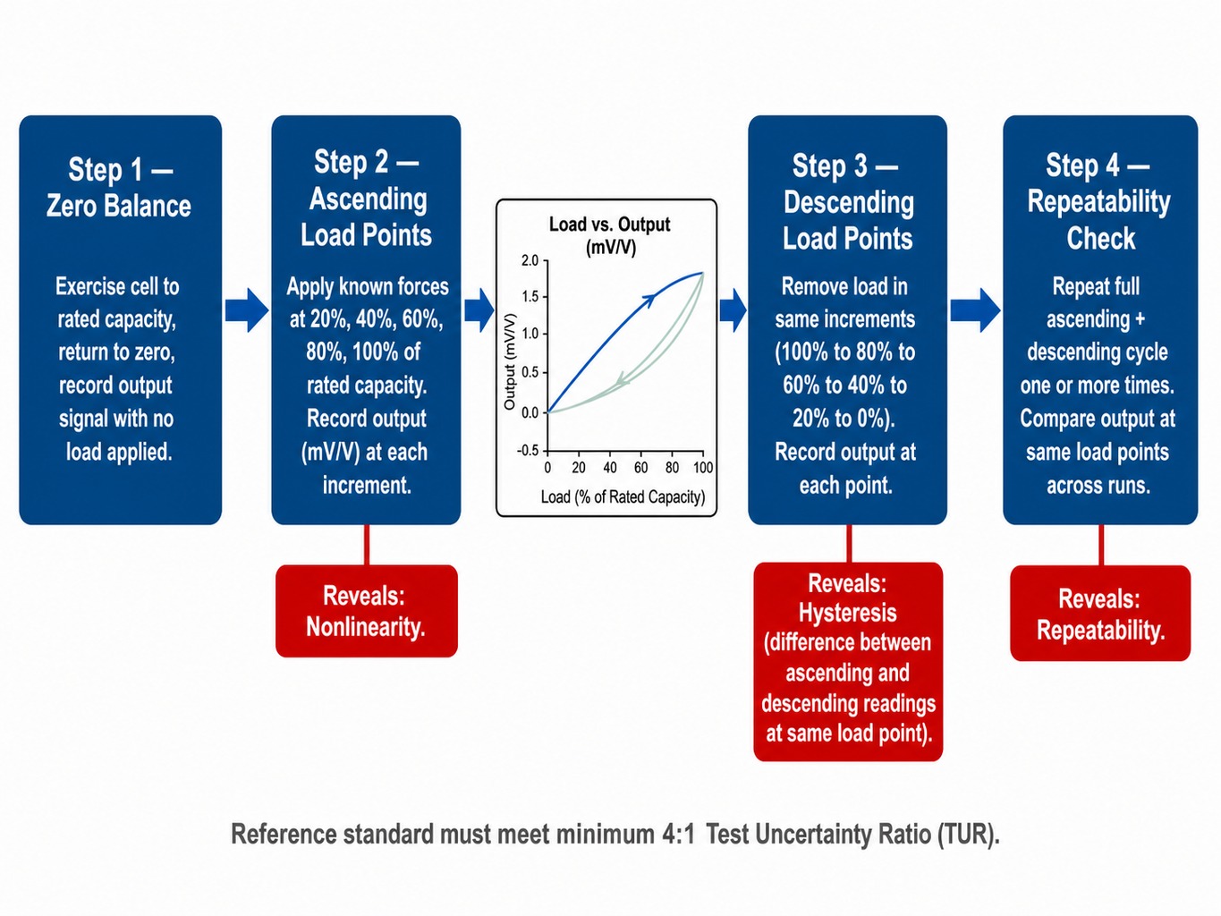 A proper multi-point calibration reveals nonlinearity, hysteresis, and repeatability in sequence.
The reference standard used to apply this force whether dead weights, a reference load cell, or a hydraulic force machine must have a known measurement uncertainty significantly smaller than the device under test. A 4:1 test uncertainty ratio (TUR) is a common minimum requirement.
Reading the Output: mV/V, Applied vs Indicated, and Combined Error
The raw data from a strain gauge load cell calibration is an electrical signal. A cell with a rated output of 2 mV/V should, in theory, produce an output of 2.000 mV/V when its full rated capacity is applied with 1 volt of excitation voltage. The mV/V output at each calibration point is the primary measurement result; any certificate that reports only converted engineering units without the raw electrical output has stripped away the information needed to evaluate the instrument's behavior independently.
This electrical output is then translated into an indicated force reading. The difference between the applied force from the reference standard and the indicated reading from the load cell system is the error at that point.
Combined error is the specification that rolls nonlinearity, hysteresis, and repeatability into a single value, typically expressed as a percentage of rated output. This is often the most useful figure on a certificate for making a quick go/no-go decision about whether the load cell meets the tolerance requirements for its specific job.
Dead Weight, Shunt Calibration, and Electronic Substitution: What Each Method Actually Tests
The term "calibration" is often used loosely to describe three very different procedures. The distinction is not academic; choosing the wrong method can create a false sense of compliance and mask serious measurement problems.
The core difference is simple:
- Dead Weight Calibration applies real, physical force and measures the load cell's complete mechanical and electrical response.
- Shunt Calibration and Electronic Substitution apply no force. They simulate an electrical signal to check the downstream electronics.
These are not interchangeable. A plant operator who relies on quarterly shunt calibration checks might assume their tank-weighing load cells are accurate, only to discover during an annual dead weight calibration that one cell has developed a severe mechanical creep problem. The shunt cal could never detect this because no actual, sustained force was ever applied.
Dead Weight Testing: The Reference Standard
Dead weight testing is the most direct and fundamental method of force calibration. It involves applying precisely known masses to the load cell, allowing gravity to generate a highly accurate and stable force. The uncertainty of this method is primarily limited by the precision of the mass standards and the knowledge of local gravitational acceleration.
This is the principle that underpins primary force standards worldwide and is referenced in key standards like ASTM E74 and ISO 376. For laboratory calibrations requiring the lowest possible uncertainty, dead weight testing is the benchmark. Its main practical limitation is physical size; dead weight machines become enormous and impractical for very high capacities, which is why hydraulic machines and master reference load cells are used for calibrating forces in the millions of pounds.
Shunt Calibration: Useful Check, Not a True Calibration
Shunt calibration is perhaps the most misunderstood procedure in the field. It does not apply any mechanical force to the sensing element. Instead, it works by connecting a high-precision resistor (the RCal resistor) across one arm of the load cell's Wheatstone bridge. This unbalances the bridge and creates a predictable change in the electrical output, simulating the signal that would be produced by a specific known load.
What does this actually verify? It confirms the integrity of the signal conditioning chain: the load cell's wiring, the connector, the cable, and the digital indicator or amplifier. It tells you the electronics are working.
What does it not verify? It tells you nothing about the load cell's mechanical response to force. A load cell with a cracked flexure, corroded strain gauges, internal moisture, or a bonding defect will often pass a shunt calibration perfectly while producing dangerously inaccurate readings under actual load. Shunt calibration is a valuable system check or troubleshooting tool, but it is not a force calibration.
Electronic Calibration Substitution: Where It Fits
Electronic calibration substitution is similar in principle to shunt calibration. It uses a precision voltage or resistance source to feed a known signal into the indicator, simulating the load cell's output at various points across its range.
Like shunt cal, it is a test of the instrumentation, not the transducer. It can be a useful way to verify the linearity and function of a digital indicator in the field, especially when applying known forces is impossible. However, it cannot replace a traceable force calibration for establishing compliance or satisfying accreditation requirements. Standards like ASTM E74 do not recognize electronic substitution as a primary calibration method for the force-measuring instrument itself.
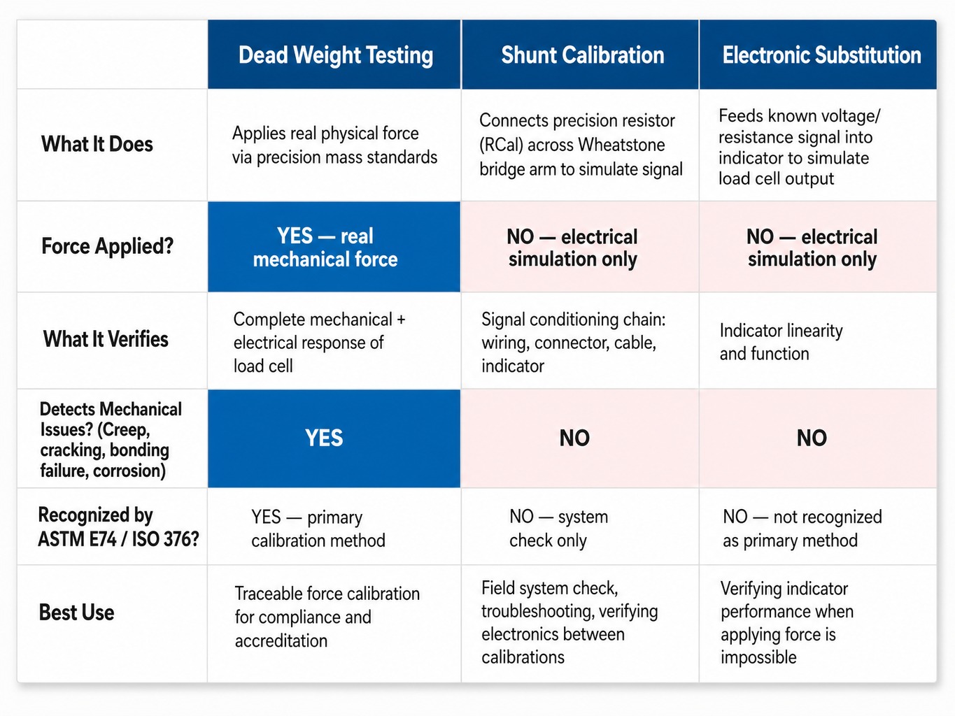
Only dead weight testing applies real force shunt and electronic methods test electronics alone.
Why Load Cells Drift After Calibration and Which Causes Matter Most
All load cells drift. It is an expected behavior, not necessarily a sign of failure. The goal of a good calibration program is to understand the rate and direction of that drift to ensure it never compromises measurement integrity. Understanding the root causes helps inform installation practices and calibration interval decisions.
While many factors contribute, a few key causes are most often missed in practice:
- Creep: When a static load is applied for a long period, the load cell's output signal will change over time. This is creep. When the load is removed, the cell may not immediately return to a perfect zero, a phenomenon known as creep recovery. A cell used for long-duration weighing in a batching system will behave differently than one used for rapid, dynamic force tests.
- Temperature Gradients: It's not just ambient temperature that matters, but thermal gradients across the load cell body. A cell mounted near a process line where one side is warmer than the other will experience differential expansion and strain, causing output drift that standard temperature compensation can't correct.
- Overload History: A single overload event, even one below the cell's specified "safe overload" rating, can cause a permanent shift in the zero balance or a change in sensitivity. These shifts are often small enough to go unnoticed until the next formal calibration.
- Mounting Errors: The load cell is part of a mechanical system. If the mounting surface deflects under load, or if the load is not applied perfectly axially (side loading), forces are introduced that the cell was not designed to measure. These errors are systematic and will persist through every calibration if the underlying mechanical issue is not fixed.
- EMC Susceptibility: Electromagnetic interference from variable frequency drives (VFDs), large motors, or radio transmitters can induce noise in the low-voltage signal from the load cell, appearing as signal drift or instability.
A batching system where load cells are recalibrated quarterly but continue to show drift is a classic example. The root cause might not be the cells themselves, but thermal gradients from a nearby steam line. In this case, shortening the calibration interval is treating the symptom, not the disease. Addressing the underlying mechanical or environmental issue often requires equipment maintenance and service beyond the calibration itself.
How to Determine the Right Calibration Interval
There is no universally correct calibration interval. Defaulting to an annual schedule without evidence is either wasteful (if the cell is highly stable) or dangerously insufficient (if the application is critical and the environment is harsh). A defensible interval is based on data, risk, and environment.
Use this three-factor framework to make an evidence-based decision:
- Drift History (Evidence-Based): This is the most important factor. By comparing the as-found data from consecutive calibrations, you can plot the instrument's drift trend. If a load cell consistently returns for calibration well within its required tolerance, the interval can likely be extended. If it is found near or beyond its tolerance limits, the interval must be shortened. This is the data-driven approach that accreditation bodies like A2LA expect to see.
- Application Risk (Risk-Based): The consequence of a bad measurement determines the required vigilance. A load cell in a legal-for-trade scale (governed by standards like OIML R60) or a safety-critical structural monitor demands a much tighter control and a more conservative interval than a cell used for low-stakes process indication.
- Environmental Severity (Condition-Based): Load cells installed in environments with high vibration, corrosive chemicals, extreme temperatures, or high moisture will degrade and drift faster than those in a climate-controlled laboratory. The interval must account for the harshness of the cell's working life.
Both ISO 9001 and ISO/IEC 17025 require organizations to have a documented basis for their calibration intervals. They do not prescribe what those intervals should be. You must be able to demonstrate that your chosen frequency is adequate to maintain measurement confidence. Finally, don't forget the hidden cost of over-calibrating: each service cycle involves downtime, labor costs, and the risk of damage during removal and reinstallation.
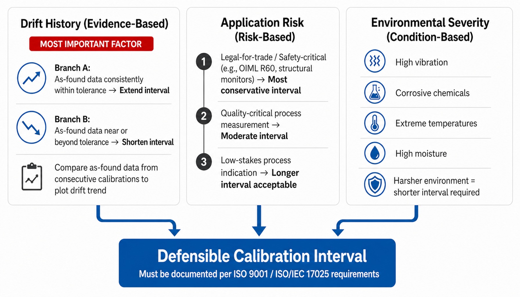
Defensible calibration intervals require evidence from drift history, risk, and environment.
Read more: Frequently Asked Questions | Cal-Cert
How to Read a Load Cell Calibration Certificate
The calibration certificate is the final product of the calibration process. It is the document that makes the measurement defensible. Yet most are filed without being read. A certificate from a non-accredited provider may be technically correct, but it will not satisfy audit requirements in many regulated industries.
An accredited ISO/IEC 17025 calibration certificate is your proof of competence and traceability. Here's what to look for:
- Unique Identification: The certificate must clearly identify the load cell (manufacturer, model, serial number) and the customer.
- Reference Standard Identification: It must identify the specific reference standards used for the calibration and their traceability to a national standards body like NIST.
- Procedure and Method: The calibration procedure followed (e.g., ASTM E74, ISO 376, or a validated internal procedure) must be stated.
- Environmental Conditions: The temperature and humidity during the calibration must be recorded, as they directly affect performance.
- As-Found and As-Left Data: The certificate must include the full data set of applied loads and instrument readings, both before and after any adjustments. A certificate with only as-left data is incomplete.
- Statement of Measurement Uncertainty: This is critical. This value represents the uncertainty of the calibration measurement itself, not the load cell's specification. It quantifies the "quality" of the calibration. A certificate without a stated measurement uncertainty is not compliant with ISO/IEC 17025.
- Accreditation Body Mark: The symbol of the accreditation body (e.g., A2LA) signifies that the laboratory's competence, procedures, and uncertainty calculations have been independently assessed and verified for the specific measurements listed in their scope of accreditation.
A quality manager preparing for an audit who discovers their certificates lack measurement uncertainty statements has a serious compliance gap, even if the load cells themselves are performing perfectly.
When the Certificate Needs to Stand Up to Scrutiny
The entire calibration process the multi-point loading, the traceable standards, the uncertainty analysis is distilled into one document: the certificate. In an audit, that document is your evidence. The question then becomes: does your calibration provider operate with the rigor required to produce a certificate that will stand up to that scrutiny?
Cal-Cert provides ISO/IEC 17025 accredited load cell calibration built on a foundation of metrological discipline. Our process uses NIST-traceable reference standards to generate certificates that include all the necessary elements for a successful audit: as-found and as-left data, a full statement of measurement uncertainty, and clear documentation of the entire traceability chain. For load cells integrated into large systems or production lines, our on-site calibration teams bring this same level of accredited rigor directly to your facility, minimizing downtime while ensuring your measurements remain defensible.
Request a calibration quote or ask about on-site service scheduling for your load cell systems.
Conclusion: Read the Certificate, Own the Data
Load cell calibration is not a stamp of approval; it is a diagnostic process that produces actionable data. The value is not in the simple pass/fail outcome but in the as-found data that shows how your instrument has been behaving, the drift trends that data reveals over time, and the traceability of the certificate that makes the entire measurement defensible.
A well-managed calibration program does more than keep equipment compliant. It provides objective evidence that an organization's critical measurements are valid and trustworthy.
The next time you receive a calibration certificate, take five minutes to read it, not just file it. Look at the as-found data. Check the uncertainty statement. Understand the story the numbers are telling you. That data is the evidence that your measurement system is under control, and ignoring it is the easiest way for a quality program to fail in silence.
Frequently Asked Questions
Can I calibrate a load cell while it is still installed in the system?
Yes, field calibration is possible using portable reference standards applied to the load cell in its installed position. However, this introduces additional uncertainty sources structural deflection, thermal gradients, and mounting alignment that are controlled in a lab. For compliance-critical applications, confirm your provider's ISO/IEC 17025 accreditation scope covers field calibration specifically.
What is the difference between ASTM E74 and ISO 376 for force calibration?
Both are standards for calibrating force instruments, but they use different classification systems and uncertainty calculations. ASTM E74 uses a Class AA/A/B system, while ISO 376 uses grades (00, 0.5, 1, 2). A load cell calibrated to one standard may not automatically meet requirements written for the other; always verify which standard your application or customer specifies.
How does temperature affect load cell calibration accuracy?
Temperature affects both the zero balance and sensitivity (span) of a load cell. Most cells have built-in temperature compensation, but it is only effective within a specified range. Calibrating at a temperature significantly different from the cell's normal operating temperature can produce results that do not reflect its real-world performance. The ambient temperature during calibration should always be recorded.
What measurement uncertainty is acceptable for load cell calibration?
There is no single acceptable value; it depends on your application's required accuracy. A common guideline is a 4:1 test uncertainty ratio (TUR), meaning the calibration process uncertainty should be at least four times smaller than the load cell's allowable error. If your process requires 0.1% accuracy, the calibration should have an uncertainty of 0.025% or better.
How do I account for hysteresis during load cell calibration?
Hysteresis is measured by comparing the load cell's output at the same applied force during the ascending (loading) and descending (unloading) parts of the calibration cycle. It cannot be adjusted out; it is an inherent mechanical characteristic. If hysteresis exceeds your application's tolerance, the load cell may need to be repaired or replaced.
How do I validate load cell calibration for legal-for-trade weighing?
Legal-for-trade applications are governed by weights and measures regulations, which often require NTEP (in the US) or OIML R60 type approval of the load cell and system. A standard calibration certificate is not enough. The entire weighing system must be tested as an installed assembly by a licensed service agent recognized by the local jurisdiction. |