

Key Takeaways
- The concrete slump test (ASTM C143) measures consistency, not workability. A true slump is the only reliable result; shear or collapse slumps indicate mix instability.
- Procedure is critical: fill the cone in three layers, rod each 25 times, and lift the cone vertically in 5 ± 2 seconds. Errors in timing or technique invalidate the test.
- Slump changes between the plant and job site due to temperature, transit time, and admixture effectiveness. Adding water on site (retempering) recovers slump but compromises strength.
- An out-of-spec result requires a defined response: verify the procedure, retest from a fresh sample, document the result, and notify the project engineer before placement.
- The test is only as reliable as the equipment. Slump cones, tamping rods, and base plates must be dimensionally verified to ensure accuracy and defensibility.
A concrete truck arrives at the job site. The inspector runs a quick field test, and the reading comes back 1.5 inches above the specified range. The pour is now on hold. The contractor is looking at standby labor costs ticking up, the driver is waiting, and the project engineer needs to make a call.
This scenario, familiar to anyone in construction quality control, hinges on the concrete slump test. It is the single most-performed check on fresh concrete, a quick "mud test" to gauge consistency before placement. But its value depends entirely on whether the procedure is executed correctly, the result is interpreted accurately, and the equipment behind it is trustworthy. A faulty number can lead to a wrongful rejection or, worse, the acceptance of a deficient mix.
This guide provides a practitioner-grade overview of the slump test. We will cover the ASTM C143 procedure step-by-step, explain what different slump types actually diagnose, identify the factors that change slump between the batch plant and the job site, and outline what to do when results fall outside specification.
What the Concrete Slump Test Actually Measures
The concrete slump test measures the consistency of fresh concrete by recording how much a molded sample subsides under its own weight after the mold is removed. The result, known as the slump value, is a single number that gives a snapshot of the concrete's fluidity at that moment.
It is critical to clarify a distinction most articles blur: slump is a proxy for consistency, not a direct measurement of workability. The two terms are often used interchangeably in the field, but they are not the same. Workability is a broader concept that includes how easily concrete can be placed, consolidated, and finished without harmful segregation. Slump captures only one dimension of that behavior its response to gravity.
The test, governed by standards like ASTM C143 and AASHTO T 119 , uses a truncated cone mold known as an Abrams cone. This cone is filled with fresh concrete in three distinct layers, with each layer being rodded 25 times to ensure proper consolidation. Once filled and struck off, the cone is lifted vertically. The vertical distance between the original height (12 inches) and the displaced center of the subsided concrete is the slump value, recorded to the nearest 1/4 inch.
Specified slump values are application-dependent. A stiff, dry mix for a slip-form paver might have a "zero slump," while a wet, flowable mix designed for a column with congested reinforcement might require a 7-inch slump. The target is set by the mix design and project requirements, not a universal standard of "good" concrete.
Equipment and Dimensional Requirements per ASTM C143
The reliability of a slump test begins with the equipment. Using a dented cone or a worn tamping rod introduces error before the test even starts. ASTM C143 specifies four required pieces of equipment and their dimensional tolerances.
- Slump Cone (Mold): The metal or plastic cone must have an inside top diameter of 4 inches, an inside base diameter of 8 inches, and a height of 12 inches. All three dimensions must be within a tolerance of ±1/8 inch. The minimum wall thickness is 0.060 inches for metal or 0.100 inches for plastic.
- Tamping Rod: A straight steel rod with a diameter of 5/8 inch and a length of approximately 24 inches. The critical feature is the tip, which must be hemispherical. A flattened or worn tip changes the compaction effort and can bias the result.
- Measuring Device: A ruler, tape, or other measuring device at least 12 inches long, with graduations in 1/4-inch increments.
- Base Plate: A flat, rigid, non-absorbent surface on which to perform the test.
As an illustrative example, during a pre-pour inspection on a bridge deck project, the slump cone in use was found to have a base diameter that measured nearly 3/16 inch undersized after years of rough handling. Every slump reading that crew had recorded for two months was suspect. The root cause was not the technician's technique. It was that nobody had verified the cone's dimensions since it was purchased. This is why having equipment dimensionally verified by an accredited lab like Cal-Cert is a fundamental part of a quality assurance program.
Read more: Construction Materials Calibration | Cal-Cert
Step-by-Step Slump Test Procedure
Performing the slump test correctly is a matter of procedural discipline. Each step has a specific parameter defined by ASTM C143, and deviating from it compromises the result.
-
Obtain the Sample: The sample must be representative of the entire batch. Per ASTM C172, take samples from at least two points in the load (e.g., after 10% and 90% of the load is discharged) and combine them in a wheelbarrow or pan. Remix the composite sample to ensure uniformity.
- Common Error: Scooping only from the first concrete to come down the chute. This portion is often mortar-rich and not representative of the full load.
-
Prepare the Equipment and Site: Dampen the inside of the cone and the base plate. Place the cone on the base plate on a level, stable surface. Stabilize the cone by standing firmly on the two foot-tabs.
- Common Error: Performing the test on uneven ground, a truck tailgate, or an absorbent surface like plywood. This allows paste to leak from the base and invalidates the test.
-
Fill the Cone in Three Layers: Fill the cone in three layers of approximately equal volume (not height). The first layer fills to a depth of about 2-5/8 inches, the second to about 6-1/8 inches, and the third to the top.
- Common Error: Filling in three equal layers by height, which results in incorrect volumes for each lift.
-
Rod Each Layer: Rod each layer exactly 25 times with the tamping rod, distributing the strokes evenly over the cross-section. For the bottom layer, rod through its full depth. For the upper two layers, penetrate the layer below by approximately 1 inch.
- Common Error: Inconsistent rodding count, jabbing aggressively, or failing to penetrate the previous layer, leading to poor consolidation and inaccurate results.
-
Strike Off and Clean: After rodding the top layer, heap concrete above the mold and strike it off flush using a screeding and rolling motion of the tamping rod. Immediately wipe away any overflow from around the base of the cone.
- Common Error: Leaving spilled concrete around the base, which can interfere with the sample's subsidence.
-
Lift the Cone: Remove your feet from the tabs and lift the cone straight up in a steady, vertical motion. Do not twist or tilt it. The lift must be completed in 5 ± 2 seconds . This timing is critical; a fast or jerky lift can introduce suction or shear forces that artificially change the slump reading.
- Common Error: Lifting the cone too quickly (e.g., in 1-2 seconds) or at a slight angle, which almost always shears the sample and produces a false high reading.
-
Measure the Slump: Immediately invert the cone and place it on the base plate next to the subsided concrete. Lay the tamping rod across the top of the inverted cone so it extends over the sample. Measure the vertical distance from the bottom of the rod to the displaced original center of the concrete. Record this value to the nearest 1/4 inch.
The entire test, from the start of filling to the final measurement, must be completed within 2.5 minutes .
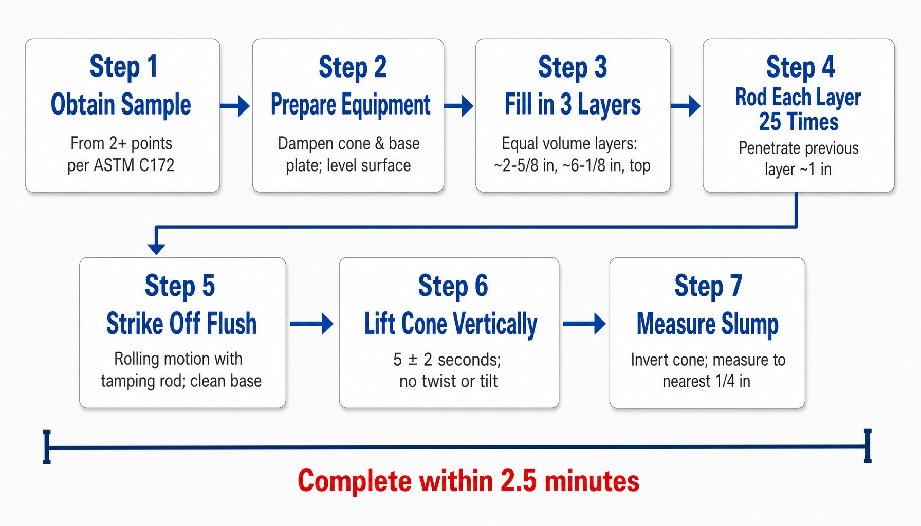
The complete slump test for concrete procedure every step and its critical parameter.
Types of Slump and What Each One Diagnoses
The slump value alone is incomplete information. How the concrete behaves when the cone is removed tells an inspector as much as the number itself. ASTM C143 recognizes three distinct patterns, but only one of them yields a valid result.
True Slump: What It Looks Like and What It Means
A true slump is the ideal and only valid outcome. The concrete subsides evenly and symmetrically, maintaining its general conical shape without significant cracking or shearing. The top surface remains roughly level.
This indicates a cohesive, well-proportioned mix where the cement paste and aggregates are working together as a stable system. A true slump is the only type that produces a reliable, reportable measurement. If the concrete does not produce a true slump, the test should be repeated. If the failure pattern persists, it signals a problem with the mix itself.
Shear Slump and Collapse: Warning Signs in the Mix
A shear slump occurs when the top portion of the concrete slides off at an angle, with one half of the cone shearing away from the other. This is not simply a "bad" result to be re-tested; it indicates a fundamental instability in the mix. It often signals that the mix lacks cohesion, is on the verge of being too wet, or has poor aggregate gradation. A shear slump is a warning sign that the mix may be prone to segregation and bleeding during placement.
A collapse slump is even more dramatic. The concrete loses all shape, flattens out, and spreads across the base plate. This signals a mix with excessive water content, an improper admixture dosage, or a fundamental lack of cohesion. A collapsed slump is not a valid test result. It means the mix is likely far outside its design water-cement ratio and should be flagged for rejection.
In either case shear or collapse the procedure is to retest on a fresh portion of the sample. If the pattern repeats, the batch is suspect and should not be placed without review.
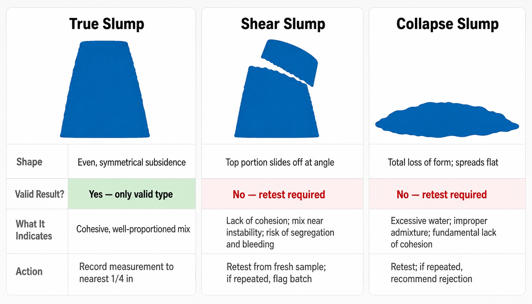
Only a true slump yields a valid concrete slump test result know the difference.
What Changes Slump Between the Batch Plant and the Job Site
The slump measured at the batch plant and the slump measured on site are almost never the same number. Understanding why is what separates a technician who records data from one who interprets it. A single rejected concrete load can cost thousands in material and delays, but the deeper risk is a dispute caused by not understanding these variables.
-
Temperature: Concrete is a chemical reaction. Higher ambient and concrete temperatures accelerate hydration, which consumes free water and causes the mix to stiffen. A load batched at 70°F that sits in 95°F heat will lose slump much faster than the same mix on a cooler day. This process is often called "slump loss."
-
Transit Time and Drum Revolutions: The longer concrete is mixed, the more slump it loses. Agitation in the truck drum continues the hydration process and can also cause minor grinding of aggregates, creating more fine particles that absorb water. For this reason, ASTM C94 sets limits on the total number of drum revolutions allowed before discharge.
-
Retempering (Adding Water): The most common and most damaging field adjustment is adding water on site to recover lost slump. While it may bring the slump reading back into the specified range, it irreversibly alters the concrete's properties. Consider a mix designed for a 0.45 water-cement (w/c) ratio. Adding just five gallons of water to a 10-yard truck can bump that ratio to nearly 0.47, directly reducing its ultimate compressive strength and long-term durability. The slump test passes, but the 28-day cylinder breaks may fail.
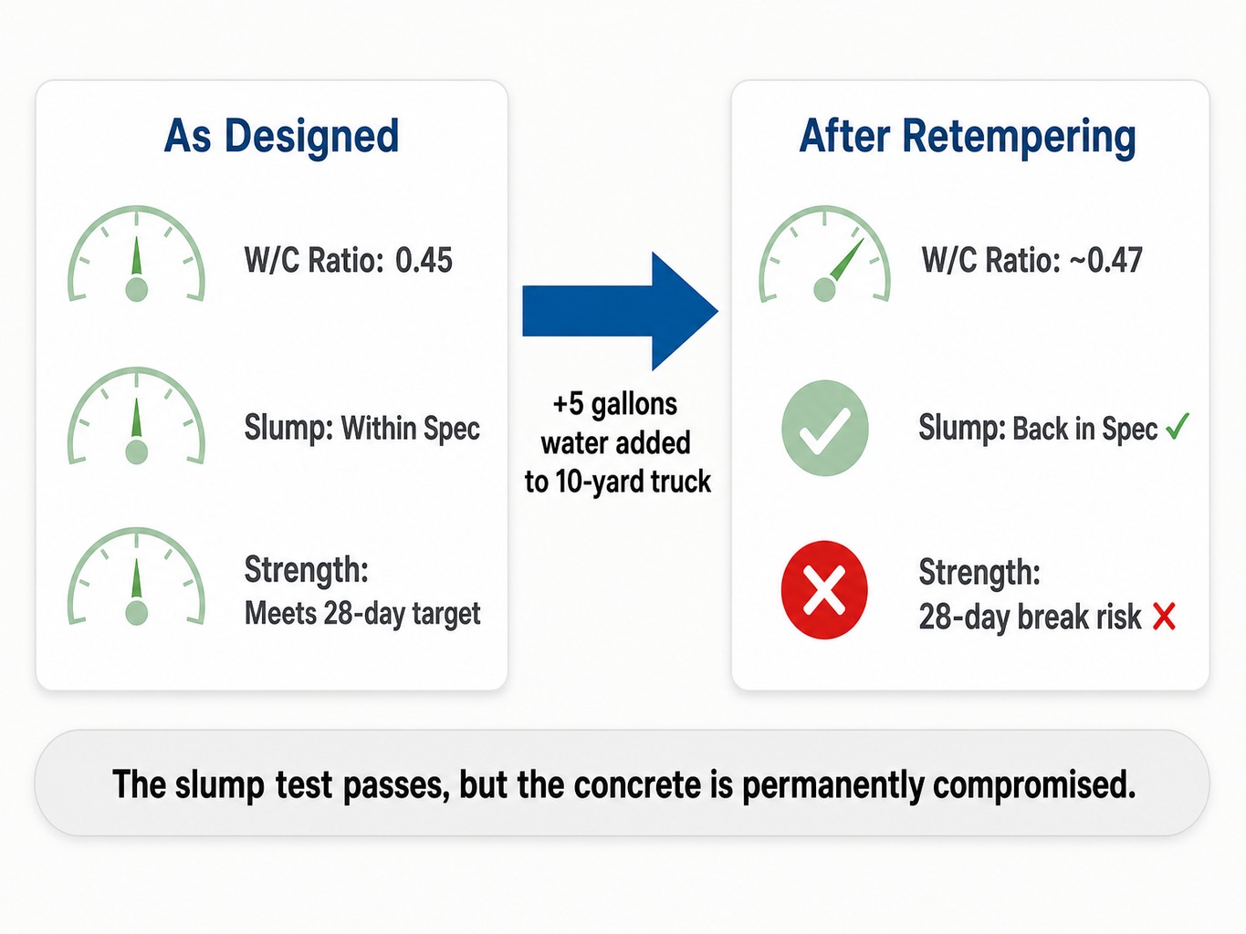
Adding water recovers slump but permanently compromises concrete strength.
- Admixture Timing: Chemical admixtures like superplasticizers (high-range water reducers) are used to increase slump significantly without adding water. However, their effect is temporary. A mix dosed at the plant may show a 7-inch slump at 20 minutes post-batching but drop to a 4-inch slump at 45 minutes. This is normal, predictable slump loss, not a mix defect.
When the Slump Test Does Not Apply
The slump test is a valuable tool, but it has clear boundaries. Using it on certain types of modern concrete produces numbers that look like data but are misleading or meaningless. Knowing when not to use the test is as important as knowing how to perform it.
-
Self-Consolidating Concrete (SCC): This highly flowable concrete is designed to spread and consolidate under its own weight without vibration. A slump test on SCC will simply collapse, yielding a result that provides no useful information. The correct test for SCC is the slump flow test (ASTM C1611) , which measures the horizontal spread diameter of the concrete.
-
Fiber-Reinforced Concrete: The addition of steel or synthetic fibers creates an internal reinforcement network that increases the apparent stiffness of the mix. This can produce artificially low slump readings that do not reflect the concrete's actual placeability. A mix with a 2-inch slump might place and consolidate perfectly well because the fibers are holding it together, making the slump reading a poor indicator of workability.
-
Very Stiff or Zero-Slump Mixes: ASTM C143 itself notes that for slumps below 1/2 inch, the test may not be meaningful as the concrete is not plastic enough to subside properly. For extremely stiff mixes like roller-compacted concrete (RCC) or dry-pack materials, alternative methods like the Vebe consistometer test or the compacting factor test provide more reliable data on consistency.
What to Do When the Slump Result Falls Outside Specification
An out-of-spec slump reading does not automatically mean the load is rejected. It means the inspector has a defined sequence of actions to ensure a defensible decision is made.
First, verify the test procedure. Was the cone lift timed correctly? Was the rodding count accurate? Was the base plate level? If any procedural step was compromised, the test is invalid. Perform a retest on a fresh portion of the sample.
Second, if the retest confirms the out-of-spec reading, document everything. Record the result, the batch ticket information (truck number, batch time, specified mix design), and the ambient conditions. Note whether the slump was a true, shear, or collapse slump.
Third, communicate the result to the project engineer, superintendent, or other responsible party before the concrete is placed. Most specifications, like ACI 301 , and project quality plans define the allowable tolerance around the target slump. Per ASTM C94, this is often ±1 inch for slumps of 3 inches or less, and ±1.5 inches for slumps over 3 inches.
Fourth, do not authorize the addition of water to the load without explicit direction from the engineer of record. If water is added, the quantity must be documented on the batch ticket, and the concrete must be retested for acceptance after the drum has revolved at least 30 times.
The Variable Most Inspectors Cannot See: Equipment Calibration
The reliability of a slump test depends on correct procedure, accurate interpretation, and understanding the factors that change slump. But one variable underlies all of these, and it is the one most often taken for granted: whether the testing equipment itself is dimensionally accurate.
A slump cone that has deformed from rough handling, a tamping rod with a worn tip, or a warped base plate introduces measurement error before the inspector even begins. This is where the chain of traceability becomes critical. Cal-Cert provides ISO/IEC 17025 accredited , NIST-traceable dimensional verification for slump cones, tamping rods, and other concrete testing equipment . This documentation ensures that your field measurements are defensible and that a dispute over a test result is not complicated by questions about the equipment's integrity. With on-site and in-lab calibration services , we help ensure your quality control program is built on a foundation of verified accuracy.
Request a calibration quote for your concrete testing equipment.
Conclusion
The concrete slump test is not a simple pass/fail check. It is a diagnostic tool whose value scales with the inspector's procedural discipline, interpretive skill, and confidence in their equipment. While straightforward to perform, the test is easy to compromise. The consequences of a bad reading whether from poor technique, incorrect timing, or uncalibrated equipment can ripple forward into placement decisions, questionable strength results, and costly project disputes.
Every slump reading is only as defensible as the chain of accuracy behind it, from the batch plant ticket to the cone's dimensions to the final calibration certificate.
Frequently Asked Questions
What slump range is typically specified for pumped concrete?
Most pump operators require a slump between 4 and 6 inches to maintain consistent flow through the line without segregation. The exact specification depends on the pump configuration, line length, and mix design, but mixes below 3 inches generally will not pump reliably.
How often should slump tests be performed during a concrete pour?
ASTM C94 requires testing at the point of delivery for the first load and then at intervals defined by the project quality plan. This is commonly for every 50 cubic yards placed or for every truck, whichever is more frequent. Testing is also required for every set of strength cylinders cast.
What does a 4-inch slump versus a 6-inch slump mean in practical terms?
A 4-inch slump indicates a moderately stiff mix suitable for general work like footings and walls. A 6-inch slump is wetter and more flowable, often specified for placements with congested reinforcement. The 2-inch difference reflects a meaningful change in water content or admixture dosage.
Can the slump test detect whether too much water was added to a mix?
It can raise a flag but cannot confirm the cause by itself. A slump reading significantly above the specified range suggests excess water, but the same reading could result from a higher admixture dose or a change in aggregate moisture. Comparing the result against the batch ticket is necessary to isolate the cause.
Is there a difference between ASTM C143 and AASHTO T 119 for the slump test?
The two standards describe essentially the same procedure and equipment. AASHTO T 119 is adopted by state departments of transportation for highway work, while ASTM C143 is used more broadly in commercial construction. A lab following one standard is generally compliant with the other.
How do you verify that a slump cone is still within ASTM dimensional tolerance?
Measure the top inside diameter (4 in), base inside diameter (8 in), and height (12 in) with a calibrated device and confirm each is within ±1/8 inch. Check the wall thickness against the minimum (0.060 in for metal). ASTM C143 requires this check at least annually, and any deformed cone should be replaced.